


In the realm of industrial automation, establishing seamless communication between Omron PLC modules and other devices is crucial for achieving efficient and reliable operations. As a trusted supplier of Omron PLC modules, I have witnessed firsthand the transformative power of well - integrated systems. In this blog, I will share insights on how to establish communication between Omron PLC modules and other devices, drawing on my experience and industry knowledge.
Understanding Omron PLC Modules
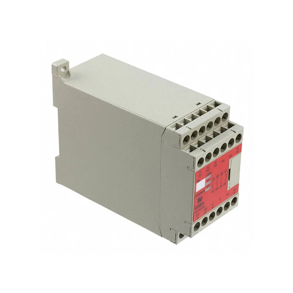
Before delving into the communication setup, it's essential to have a basic understanding of Omron PLC modules. Omron offers a wide range of PLC modules, each designed for specific functions and applications. For example, the CP1W - DA041 Omron is a popular analog output module that can convert digital signals from the PLC into analog signals, which are often used to control devices such as motors or valves. The Omron CP2E - N30DR - A is a compact PLC unit with built - in I/O points, suitable for small - to - medium - sized automation projects. And the G9SA - 321 - T075 AC/DC24 Omron is a reliable relay module that can be used to control high - power devices.
Communication Protocols
Omron PLC modules support various communication protocols, and choosing the right one is the first step in establishing communication with other devices.
Ethernet/IP
Ethernet/IP is a widely used industrial Ethernet protocol. It allows Omron PLCs to communicate with other Ethernet - enabled devices such as human - machine interfaces (HMIs), variable frequency drives (VFDs), and other PLCs. To use Ethernet/IP for communication, you need to configure the IP addresses of the Omron PLC and the connected devices. In the Omron programming software, you can set up the Ethernet/IP parameters, including the subnet mask, gateway, and device addresses. Once the configuration is complete, the PLC can exchange data with other devices on the network.
Modbus TCP
Modbus TCP is another popular protocol for industrial communication. It is a simple and easy - to - implement protocol that allows Omron PLCs to communicate with Modbus - compatible devices. To establish Modbus TCP communication, you need to configure the Omron PLC as a Modbus TCP server or client. If the PLC is set as a server, it will listen for incoming requests from other devices. If it is set as a client, it will initiate requests to the Modbus - compatible devices. You also need to define the Modbus addresses of the data registers in the PLC and the connected devices.
Profibus
Profibus is a fieldbus protocol commonly used in European industrial applications. Omron offers PLC modules with Profibus interfaces that can communicate with Profibus - enabled devices such as sensors, actuators, and other control systems. When using Profibus, you need to configure the Profibus network parameters, including the baud rate, station addresses, and data format. The Omron programming software provides tools for setting up Profibus communication, and you can monitor the communication status and troubleshoot any issues.
Hardware Connection
In addition to choosing the right communication protocol, proper hardware connection is also essential for establishing communication.
Ethernet Connection
For Ethernet - based communication protocols such as Ethernet/IP and Modbus TCP, you need to connect the Omron PLC to the network using an Ethernet cable. Make sure the cable is properly plugged into the Ethernet port of the PLC and the network switch. You may also need to use a crossover cable if you are directly connecting the PLC to another device without a network switch.
Serial Connection
Some Omron PLC modules support serial communication protocols such as Modbus RTU. To establish a serial connection, you need to use a serial cable, such as an RS - 232 or RS - 485 cable, depending on the requirements of the connected devices. When using an RS - 485 connection, you need to pay attention to the proper termination of the cable to avoid signal reflection and interference.
Fieldbus Connection
When using fieldbus protocols like Profibus, you need to connect the Omron PLC to the fieldbus network using a fieldbus cable. The fieldbus cable should be properly terminated at both ends of the network. You also need to ensure that the fieldbus couplers and connectors are correctly installed and configured.
Software Configuration
After the hardware connection is complete, you need to configure the Omron PLC software to enable communication with other devices.
Omron Programming Software
Omron provides programming software such as CX - Programmer or Sysmac Studio, depending on the type of PLC module. In the programming software, you can create a new project and configure the communication settings. You can define the communication protocol, set the device addresses, and map the data registers between the PLC and the connected devices.
Data Mapping
Data mapping is an important step in software configuration. You need to define which data in the PLC will be sent to the connected devices and which data will be received from the devices. For example, if you are using an analog output module to control a motor speed, you need to map the data register in the PLC that stores the speed setpoint to the corresponding input register in the motor controller.
Testing and Debugging
Once the software configuration is complete, it's time to test the communication. You can use the monitoring and diagnostic tools in the Omron programming software to check the communication status and data exchange. If there are any issues, you can use the debugging features to troubleshoot the problem. Check the error messages in the software, verify the hardware connections, and review the communication settings.
Troubleshooting Common Issues
Even with proper configuration, you may encounter some common issues when establishing communication between Omron PLC modules and other devices.
Communication Errors
If you receive communication error messages, first check the hardware connections. Make sure the cables are properly plugged in and there are no loose connections. Check the power supply of the devices to ensure they are working properly. Also, verify the communication settings in the Omron programming software, including the protocol selection, device addresses, and data format.
Data Inconsistency
Data inconsistency can occur if the data mapping is incorrect or if there are issues with the communication protocol. Review the data mapping in the programming software and make sure the data registers in the PLC and the connected devices are correctly mapped. Check the communication protocol settings to ensure that the data is being transmitted and received correctly.
Network Interference
Network interference can affect the communication quality. If you are using Ethernet - based communication, make sure the network is free from electromagnetic interference. Avoid running Ethernet cables near high - power electrical equipment. If you are using a wireless network, check the signal strength and interference from other wireless devices.
Conclusion
Establishing communication between Omron PLC modules and other devices is a multi - step process that requires careful consideration of communication protocols, hardware connection, software configuration, and troubleshooting. As an Omron PLC module supplier, I am committed to providing high - quality products and technical support to help you achieve seamless communication in your industrial automation projects. Whether you are a small - scale manufacturer or a large - scale industrial enterprise, our Omron PLC modules can meet your diverse automation needs.
If you are interested in purchasing Omron PLC modules or need more information on establishing communication between Omron PLC modules and other devices, please feel free to contact us for procurement and consultation. We look forward to working with you to build efficient and reliable industrial automation systems.
References
- Omron Corporation. Omron PLC User Manuals.
- Industrial Communication Protocols Handbook.
- Ethernet/IP and Modbus TCP Technical Guides.


