


As a reputable supplier of Omron PLC modules, I understand the importance of proper wiring for these devices. Wiring an Omron PLC module correctly is crucial for ensuring its optimal performance and longevity. In this blog post, I will guide you through the process of wiring an Omron PLC module, covering everything from understanding the basics to troubleshooting common issues.
Understanding the Basics of Omron PLC Modules
Before you start wiring an Omron PLC module, it's essential to have a basic understanding of how these modules work. Omron PLC modules are used in industrial automation to control and monitor various processes. They consist of input and output modules that connect to sensors and actuators, allowing the PLC to receive data and send commands.
Tools and Materials You'll Need
- Screwdriver: For removing and installing terminal blocks.
- Wire strippers: To strip the insulation from the wires.
- Multimeter: To test the continuity and voltage of the wires.
- Omron PLC module: The specific module you'll be wiring.
- Power supply: A suitable power supply for the PLC module.
- Wiring cables: Appropriate cables for connecting the module to the sensors and actuators.
Step-by-Step Wiring Guide
Step 1: Prepare the Work Area
Ensure that the work area is clean, dry, and well-lit. Turn off the power supply to the PLC system to prevent any electrical accidents.
Step 2: Identify the Input and Output Terminals
Locate the input and output terminals on the Omron PLC module. These terminals are usually labeled clearly on the module. The input terminals are used to connect sensors, while the output terminals are used to connect actuators.
Step 3: Strip the Wires
Use wire strippers to strip about 1/2 inch of insulation from the ends of the wires. Make sure the wires are clean and free of any debris.
Step 4: Connect the Power Supply
Connect the power supply to the appropriate terminals on the PLC module. Refer to the module's documentation for the correct wiring diagram. Ensure that the power supply voltage matches the requirements of the module.
Step 5: Connect the Input Sensors
Connect the sensors to the input terminals on the PLC module. Each sensor should be connected to a separate input terminal. Use the multimeter to test the continuity of the wires to ensure they are properly connected.
Step 6: Connect the Output Actuators
Connect the actuators to the output terminals on the PLC module. Similar to the input sensors, each actuator should be connected to a separate output terminal. Again, use the multimeter to test the continuity of the wires.
Step 7: Secure the Wires
Use cable ties or wire clips to secure the wires and prevent them from moving or coming loose. This will help to maintain a reliable connection and prevent any short circuits.
Step 8: Double-Check the Wiring
Before turning on the power supply, double-check all the connections to ensure they are correct. Look for any loose wires, incorrect connections, or signs of damage.
Step 9: Power On the PLC System
Once you have verified that all the connections are correct, turn on the power supply to the PLC system. Monitor the module for any error messages or abnormal behavior.

Troubleshooting Common Wiring Issues
- No Power: Check the power supply connections and ensure that the voltage is correct. Use a multimeter to test the power supply.
- Input or Output Not Working: Check the connections between the sensors or actuators and the PLC module. Make sure the wires are properly connected and there are no breaks in the circuit.
- Short Circuits: Look for any signs of damage or loose wires that could be causing a short circuit. Use a multimeter to test for continuity between the terminals.
Recommended Omron PLC Modules
As a supplier, I recommend the following Omron PLC modules for various applications:
- Omron C200H-ID211 PLC: This module is suitable for general input applications and offers reliable performance.
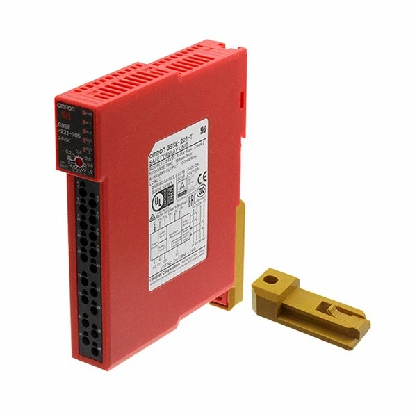
- G9SE-221-T30 DC24 OMRON: Ideal for applications that require precise timing and control.
- Omron C200H-0D218: A versatile output module that can be used in a wide range of industrial automation applications.
Conclusion
Wiring an Omron PLC module may seem daunting at first, but by following the steps outlined in this blog post and using the right tools and materials, you can ensure a successful installation. Remember to always refer to the module's documentation for specific wiring instructions and safety guidelines.
If you have any questions or need further assistance with wiring an Omron PLC module or are interested in purchasing Omron PLC modules, please feel free to contact us for procurement and negotiation. We are here to help you find the best solutions for your industrial automation needs.
References
- Omron Corporation. Omron PLC Module User Manuals.
- Industrial Automation Handbook. Various Editions.


