


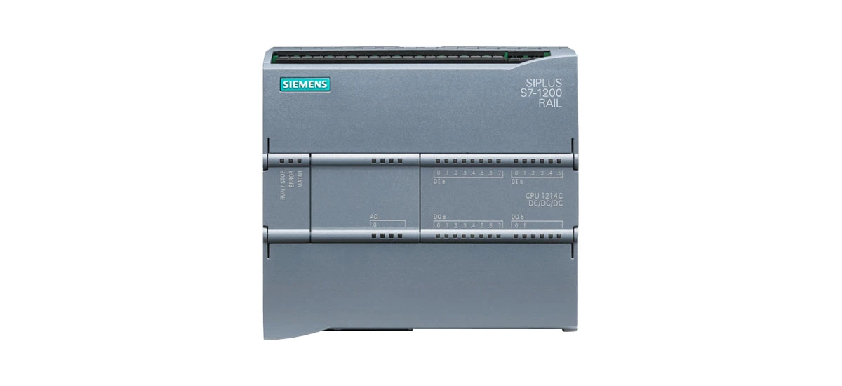
Are you experiencing frustrating issues with your Siemens S7-1200 PLC system? When your industrial automation equipment suddenly stops working correctly, it can bring your entire production line to a halt, causing costly downtime and operational delays. As one of Siemens' most popular compact controllers, the S7-1200 PLC is known for its reliability and performance in industrial environments. However, like any sophisticated electronic equipment, it can occasionally encounter technical problems that require troubleshooting.
This comprehensive guide will walk you through identifying and resolving the most common Siemens S7-1200 errors with clear, step-by-step instructions. Whether you're a maintenance technician, plant engineer, or automation specialist, understanding how to systematically diagnose and fix these issues will significantly reduce your equipment downtime and keep your operations running efficiently.
Understanding the Siemens S7-1200 Status Lights and Diagnostic Indicators
The status lights on your Siemens S7-1200 PLC serve as the primary communication channel between the equipment and the operator. Learning to interpret these visual cues correctly is the crucial first step in effective troubleshooting.
- RUN/STOP Indicator Analysis: The solid green light indicates normal operation with program execution running smoothly. When you see a steady orange light, this means the PLC is in STOP mode, which could be intentional or caused by a program error. If the LED flashes red at approximately 1-second intervals, this typically indicates a hardware configuration error or significant software problem that requires immediate investigation.
- ERROR Indicator Interpretation: A continuously illuminated red ERROR light often suggests serious hardware damage or critical system failure. When this light flashes red, it usually indicates a recoverable error such as a program logic conflict, communication timeout, or peripheral device issue. In flashing mode, the CPU typically remains in RUN state but may have limited functionality until the underlying issue is resolved.
- MAINT Indicator Functionality: On newer S7-1200 CPUs, the yellow MAINT light provides additional diagnostic information. When this light is active, it indicates that maintenance is required, often related to firmware updates, memory card issues, or system configuration changes that need attention.
- DIAG Indicator Significance: This yellow diagnostic light illuminates when the CPU is performing self-tests or system diagnostics. If it remains lit for extended periods, it suggests the system is detecting and logging multiple minor errors that could develop into more serious problems if left unaddressed.
Regularly monitoring these status indicators during normal operation will help you establish a baseline, making it easier to spot abnormal patterns when problems occur with your Siemens S7-1200 system.
Common Siemens S7-1200 Communication Problems and Connection Issues
Communication failures represent one of the most frequent categories of problems encountered with Siemens S7-1200 PLC systems in industrial environments. These issues can manifest in various ways, each requiring specific diagnostic approaches and solutions.
Network Connectivity and Ethernet Communication Problems
When your Siemens S7-1200 PLC cannot establish or maintain network connections, start with these diagnostic steps:
- Physical Connection Verification: Begin by inspecting all Ethernet cables for visible damage, secure connections, and proper routing away from power cables and sources of electrical interference. Test cable continuity using a network cable tester if available. Replace any cables showing signs of wear, crushing, or connector damage.
- IP Address Configuration Issues: Confirm that your Siemens S7-1200 CPU has a unique IP address within your network range. Check for IP address conflicts by pinging the address from another network device. Verify that the subnet mask and gateway settings match your network configuration requirements. Use the TIA Portal's "Online Access" feature to scan for accessible devices and compare detected IP addresses with your project configuration.
- PROFINET Communication Failures: For PROFINET network issues, verify that all devices have correct device names and that these names match the configuration in your hardware catalog. Check that the PROFINET interface settings, including update time and station type, are properly configured for your network topology.
Programming and Configuration Communication Challenges
Software-related communication problems often stem from configuration mismatches or programming oversights:
- Data Block Access Configuration: The "Symbolic access only" option for data blocks frequently causes communication problems. When this option is enabled, the data block cannot be accessed via absolute addressing, which affects pointer-type communication instructions. To resolve this, recreate the data block without selecting the "Symbolic access only" option, or modify your communication instructions to use symbolic addressing consistently throughout your Siemens S7-1200 program.
- Communication Instruction Execution: Many communication instructions, such as TCON, TUSEND, and TURCV, require proper management of the REQ (request) parameter. These instructions typically execute only when they detect a rising edge (transition from 0 to 1) on the REQ input. If REQ remains at "1", the instruction executes only once. Implement edge detection logic or use clock memory bits to trigger these instructions periodically for ongoing communication tasks.
- Buffer Management and Data Alignment: For TCP communication, ensure that the send and receive buffer sizes match exactly between communication partners. Data misalignment occurs when buffers are different sizes, causing shifted or truncated data. Always verify that the data area and receiving area are identical in length and data type definition to maintain proper Siemens S7-1200 communication setup.
Program Execution Issues and CPU Performance Problems
Program-related errors can cause unexpected CPU behavior, including slow performance, unexpected stops, or erratic operation. Understanding how to diagnose these issues is essential for maintaining reliable automation systems.
Scan Time Violations and Cycle Time Monitoring
The Siemens S7-1200 monitors program execution time to ensure predictable system behavior:
- Cycle Time Exceeded Responses: When your program scan time exceeds the maximum cycle time configured in the CPU properties (default is 150ms), the system responds based on the severity of the violation. For minor exceedances, the ERROR LED typically flashes six times while the CPU remains in RUN mode. If the cycle time exceeds twice the maximum cycle time setting, the CPU may transition to STOP mode to prevent unpredictable operation.
- Cycle Time Monitoring Configuration: Adjust the maximum cycle time setting in the CPU configuration under "Cycle time" settings in TIA Portal. For applications with varying processing demands, consider implementing the cycle time monitoring with Organization Block OB80, which allows you to program custom responses to time violations rather than allowing the CPU to stop unexpectedly.
- Performance Optimization Techniques: If you're experiencing consistent cycle time problems, optimize your program by dividing large logic sections into multiple program cycle OBs with different execution priorities. Use bit memory and data blocks strategically to minimize direct I/O access during the main program scan. For time-critical functions, consider using interrupt OBs (such as time-of-day or time-delay interrupts) to handle specific tasks outside the main program cycle.
CPU Operating Mode Issues and STOP Condition Analysis
Unexpected CPU stops represent some of the most disruptive problems in automation systems:
- Diagnostic Buffer Analysis: When your Siemens S7-1200 CPU enters STOP mode unexpectedly, the diagnostic buffer becomes your most valuable troubleshooting tool. Connect to the CPU using TIA Portal and navigate to "Online & diagnostics" to access this feature. The diagnostic buffer maintains a time-stamped log of operating mode changes, error events, and system messages that led to the STOP condition.
- STOP Cause Investigation: Common causes of unexpected STOP conditions include programming errors (accessing invalid memory areas), hardware configuration mismatches, missing hardware components, or severe communication faults. The diagnostic buffer entry corresponding to the STOP event typically provides specific error codes that you can research in Siemens documentation or knowledge base articles.
- Firmware Compatibility Verification: Ensure that your project configuration matches the actual firmware version of your Siemens S7-1200 CPU. Mismatched firmware versions can cause various operational problems, including unexpected stops. Use TIA Portal's "Accessible devices" feature to read the actual firmware version from the CPU, then either update the CPU firmware or adjust your project configuration to match.
Advanced Diagnostic Techniques and Error Handling
Implementing proactive diagnostic strategies can help you identify potential problems before they cause significant downtime in your Siemens S7-1200 system.
Diagnostic Error Interrupts and Hardware Diagnostics
The Siemens S7-1200 provides sophisticated diagnostic capabilities through dedicated organization blocks and hardware features:
- OB82 Diagnostic Error Interrupt Implementation: Configure supported modules to generate diagnostic error interrupts by enabling the diagnostic functions in the hardware configuration. When a configured diagnostic event occurs, the CPU interrupts the normal program scan to execute OB82, allowing you to implement custom diagnostic routines. Common triggering events include module power loss, signal overrange/underrange conditions, sensor wire breaks, and output short circuits.
- Diagnostic Data Interpretation: When OB82 is triggered, it provides specific information about the diagnostic event through its start information and temporary local data. Program OB82 to read the module-specific diagnostic data, which typically includes details about the affected module, channel, and exact nature of the problem. Store this information in a dedicated data block for trend analysis and preventive maintenance planning.
- System Diagnostic Functions: Utilize the system diagnostic functions available in TIA Portal, including the "Hardware diagnostics" view, which provides a visual representation of your configuration with color-coded status indicators for each module. This feature quickly directs your attention to problematic components, speeding up the Siemens S7-1200 troubleshooting process.
Comprehensive Step-by-Step Troubleshooting Methodology
Develop a systematic approach to Siemens S7-1200 troubleshooting to ensure no potential causes are overlooked:
Step 1: Initial Status Assessment: Document all status LED indications on the CPU and any connected signal modules. Note any abnormal blinking patterns or unexpected LED states. Compare these observations with the LED status descriptions in the Siemens S7-1200 system manual to narrow down potential issue categories.
Step 2: TIA Portal Diagnostic Tools Utilization: Establish an online connection to the CPU using TIA Portal. Navigate to the "Online & diagnostics" view and examine the diagnostic buffer entries chronologically, starting with the most recent events. Use the "Hardware detection" feature if module configuration mismatches are suspected.
Step 3: Systematic Hardware Inspection: Perform a thorough physical inspection of all system components. Verify proper power supply voltage (20.4V to 28.8V DC for standard modules) at the CPU and expansion modules. Check for secure module installation and proper engagement of the internal bus connectors. Inspect all field wiring connections for tightness and proper termination.
Step 4: Program Logic and Configuration Review: If hardware issues are ruled out, examine your program logic for potential problems. Verify that all required Organization Blocks are present in your project. Check for correct handling of error OBs (such as OB80, OB82, OB86, OB121, and OB122). Confirm that data block access is configured appropriately for your communication needs.
Step 5: Firmware and Project Compatibility Verification: Ensure firmware consistency throughout your system. Update CPU and module firmware to recommended versions if necessary. Verify that the configured module versions in your hardware configuration match the actual installed hardware. Resolve any detected inconsistencies through hardware configuration adjustments or firmware updates.
Preventive Maintenance Strategies for Siemens S7-1200 Systems
Implementing a proactive maintenance program can significantly reduce unexpected failures and extend the service life of your Siemens S7-1200 equipment:
- Regular Backup Procedures: Maintain a disciplined backup strategy for all project files, including regular archives of program modifications, hardware configurations, and documentation. Store backups in multiple locations, including off-site storage, to protect against data loss from equipment failure or facility incidents.
- Environmental Condition Monitoring: Ensure your control cabinet environment remains within specified limits (operating temperature 0-55°C, relative humidity ≤95% non-condensing). Install temperature monitoring with alert thresholds to detect cooling system degradation before it affects operation. Maintain adequate clearance around ventilation openings and periodically clean air filters on cabinet cooling systems.
- Power Quality Management: Use industrial-grade power conditioning equipment to protect against voltage spikes, sags, and electrical noise. Implement regular power quality verification using true-RMS multimeters or power quality analyzers. Consider installing uninterruptible power supplies (UPS) for critical applications to ensure continuous operation during brief power interruptions.
- Electromagnetic Compatibility Measures: Properly ground all equipment according to Siemens installation guidelines. Use shielded cables for analog signals and communication networks, with proper shield termination at one end only. Maintain physical separation between power and signal cables, crossing them at right angles when routing proximity is unavoidable.
- Preventive Maintenance Scheduling: Establish a regular maintenance schedule that includes visual inspections, connection verification, firmware version reviews, and diagnostic buffer analysis. Document all maintenance activities and resolved issues to build a historical record for trend analysis and future troubleshooting reference.
Advanced Support Resources and Next Steps
When standard troubleshooting approaches don't resolve your Siemens S7-1200 problems, additional resources are available:
- Siemens Technical Support Services: For complex issues beyond the scope of standard troubleshooting, contact Siemens technical support with detailed information about your problem, including diagnostic buffer contents, project configuration details, and steps already taken to resolve the issue.
- Specialized Diagnostic Tools: Consider investing in advanced diagnostic equipment such as industrial Ethernet analyzers, protocol analyzers, or Siemens-specific service tools for complex network issues or intermittent problems that are difficult to reproduce.
- Training and Certification Opportunities: Enhance your troubleshooting skills through Siemens SITRAIN certification programs, which provide hands-on training with S7-1200 systems and deepen your understanding of diagnostic techniques and best practices for maintaining Siemens automation equipment.
Conclusion: Mastering Siemens S7-1200 Troubleshooting
Effective troubleshooting of Siemens S7-1200 systems requires a methodical approach, starting with simple visual inspections and progressing to advanced diagnostic techniques when necessary. By understanding how to interpret status indicators, utilize TIA Portal diagnostic features, and implement systematic troubleshooting procedures, you can quickly identify and resolve most common problems.
Remember that preventive maintenance and proper documentation significantly reduce both the frequency and severity of system issues. Regular backups, environmental monitoring, and proactive component inspection will help maintain your Siemens S7-1200 system at peak performance while minimizing unexpected downtime.
As you gain experience with Siemens S7-1200 troubleshooting, you'll develop intuition for recognizing patterns in system behavior that signal developing problems before they cause significant disruptions. This proactive approach to system maintenance ensures maximum reliability and performance from your industrial automation equipment.


