


Establishing a connection between a Mitsubishi HMI (Human-Machine Interface) and a PLC (Programmable Logic Controller) is a crucial step in industrial automation systems. As a Mitsubishi HMI supplier, I have extensive experience in guiding customers through this process. In this blog, I will share a step-by-step guide on how to establish this connection, ensuring seamless communication and efficient operation of your industrial equipment.
Understanding the Basics
Before diving into the connection process, it's essential to understand the roles of the HMI and PLC in an industrial automation system. The PLC is the brain of the operation, responsible for controlling and monitoring various industrial processes. It receives input signals from sensors, processes this information according to a pre-programmed logic, and then sends output signals to actuators to perform specific tasks.
On the other hand, the HMI serves as the interface between the operator and the PLC. It allows operators to monitor the status of the PLC, input commands, and view data in a user-friendly format. By establishing a connection between the HMI and PLC, operators can interact with the industrial processes in real-time, making adjustments as needed to ensure optimal performance.
Selecting the Right HMI and PLC
The first step in establishing a connection is to select the appropriate Mitsubishi HMI and PLC for your application. Mitsubishi offers a wide range of HMIs and PLCs, each with different features and capabilities. Some popular models include the Mitsubishi Gs2110-Wtbd Touch Screen, MITSUBISHI GT1662-VNBA Touch Screen, and Mitsubishi GOT 1000 GT1695M-XTBA.

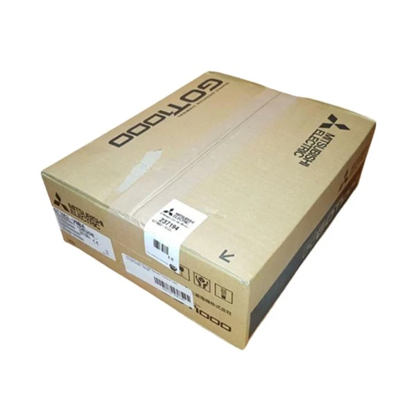
When selecting an HMI, consider factors such as screen size, resolution, touch functionality, and communication interfaces. For the PLC, consider the number of input/output points, processing speed, and programming capabilities. Ensure that both the HMI and PLC support the same communication protocol, as this is essential for establishing a successful connection.
Choosing the Communication Protocol
Mitsubishi HMIs and PLCs support several communication protocols, including Ethernet, serial communication (RS-232, RS-422, RS-485), and USB. The choice of protocol depends on factors such as the distance between the HMI and PLC, the required data transfer rate, and the existing infrastructure.
- Ethernet: Ethernet is a popular choice for high-speed communication over long distances. It offers fast data transfer rates and is compatible with most modern HMIs and PLCs. To use Ethernet, both the HMI and PLC must have Ethernet ports and be configured with the same IP address settings.
- Serial Communication: Serial communication is suitable for shorter distances and applications where a lower data transfer rate is acceptable. RS-232 is commonly used for point-to-point communication, while RS-422 and RS-485 can support multiple devices on the same network.
- USB: USB is a convenient option for connecting the HMI and PLC directly. It offers fast data transfer rates and is easy to set up. However, the distance between the HMI and PLC is limited by the length of the USB cable.
Configuring the HMI
Once you have selected the HMI and PLC and chosen the communication protocol, the next step is to configure the HMI for the connection. This involves setting up the communication parameters, creating screen objects, and defining the data transfer between the HMI and PLC.
- Communication Settings: Open the HMI configuration software and navigate to the communication settings section. Select the appropriate communication protocol and enter the required parameters, such as IP address, subnet mask, and gateway for Ethernet, or baud rate, parity, and stop bits for serial communication.
- Screen Object Creation: Create screen objects on the HMI, such as buttons, indicators, and text boxes, to allow operators to interact with the PLC. Assign the appropriate memory addresses in the PLC to these screen objects to enable data transfer.
- Data Transfer Definition: Define the data transfer between the HMI and PLC by specifying the memory areas and addresses to be read and written. This ensures that the HMI can display the correct data from the PLC and send commands to the PLC as needed.
Configuring the PLC
After configuring the HMI, the next step is to configure the PLC for the connection. This involves enabling the communication function, setting up the communication parameters, and programming the PLC to respond to commands from the HMI.
- Communication Function Enable: In the PLC programming software, enable the communication function for the selected protocol. This may involve setting up the communication module and configuring the communication parameters.
- Communication Parameter Setup: Enter the same communication parameters as those set on the HMI, such as IP address, subnet mask, and gateway for Ethernet, or baud rate, parity, and stop bits for serial communication.
- PLC Programming: Program the PLC to respond to commands from the HMI and send data to the HMI as needed. This may involve writing ladder logic programs or using function blocks to perform specific tasks.
Testing the Connection
Once both the HMI and PLC are configured, it's time to test the connection. Power on both the HMI and PLC and check if they can communicate with each other. You can do this by checking the status indicators on the HMI and PLC, or by using diagnostic tools in the configuration software.
If the connection is successful, you should be able to view the data from the PLC on the HMI and send commands from the HMI to the PLC. If there are any issues, double-check the communication settings on both the HMI and PLC, and ensure that the cables are properly connected.
Troubleshooting Common Issues
Even with proper configuration, you may encounter some issues when establishing a connection between the HMI and PLC. Here are some common issues and their possible solutions:
- Communication Failure: If the HMI and PLC cannot communicate, check the communication settings, cables, and network connections. Ensure that both devices are powered on and that the communication protocol is correctly configured.
- Data Transfer Errors: If there are errors in the data transfer between the HMI and PLC, check the memory addresses assigned to the screen objects and the data transfer definitions. Ensure that the data types and formats are compatible between the HMI and PLC.
- Screen Object Malfunction: If the screen objects on the HMI are not working correctly, check the programming of the screen objects and the assigned memory addresses in the PLC. Ensure that the PLC is responding to the commands from the HMI.
Conclusion
Establishing a connection between a Mitsubishi HMI and PLC is a straightforward process when you follow the right steps. By selecting the appropriate HMI and PLC, choosing the right communication protocol, and configuring both devices correctly, you can ensure seamless communication and efficient operation of your industrial automation system.
If you have any questions or need assistance in selecting the right Mitsubishi HMI and PLC for your application, or in establishing a connection between them, please feel free to contact us. We are here to help you make the most of your industrial automation investment.
References
- Mitsubishi Electric Corporation. (Year). Mitsubishi HMI and PLC User Manuals.
- Industrial Automation Handbook. (Year). Various Authors.


