


Hey there! I'm a supplier of Mitsubishi HMI, and today I'm gonna share with you how to set up the communication parameters between Mitsubishi HMI and PLC. It might seem a bit tricky at first, but once you get the hang of it, it's not that hard.
First off, let's understand why setting up these communication parameters is so important. The HMI (Human - Machine Interface) and the PLC (Programmable Logic Controller) work hand - in - hand in an industrial automation system. The HMI allows operators to interact with the system, monitor processes, and control the PLC. The PLC, on the other hand, is responsible for executing logic operations and controlling the machinery. If the communication between them isn't set up correctly, the whole system won't function as it should.
Step 1: Choose the Right HMI and PLC
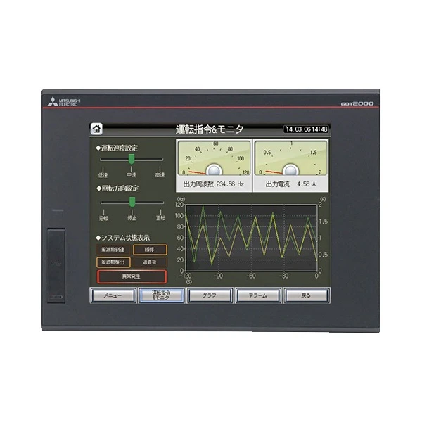
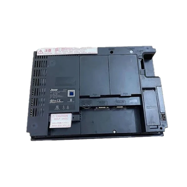
Before you start setting up the communication parameters, you need to make sure you have the right HMI and PLC. Mitsubishi offers a wide range of HMIs, like the Mitsubishi GT2710 - STBA GOT2000, Mitsubishi GT2510 - VTWD, and Mitsubishi GT2512 - STBD HMI. Each HMI has its own features and capabilities, so you need to choose one that suits your specific application.
When it comes to the PLC, Mitsubishi also has a variety of models. You need to ensure that the HMI and the PLC are compatible with each other. Check the product manuals to see which PLC models are supported by your chosen HMI.
Step 2: Physical Connection
The first step in setting up the communication is to make the physical connection between the HMI and the PLC. Usually, Mitsubishi HMIs and PLCs can be connected using serial cables or Ethernet cables.
If you're using a serial connection, you'll need to connect the serial ports of the HMI and the PLC. Make sure the pins are properly connected according to the wiring diagram in the product manual. Serial connections are relatively simple but may have limitations in terms of speed and distance.
For Ethernet connections, you'll need to connect the Ethernet ports of both devices using an Ethernet cable. Ethernet connections offer higher speed and longer distances, which is great for larger industrial systems.
Step 3: Configure the HMI
Once the physical connection is made, it's time to configure the HMI. The configuration process can be done using the HMI's programming software.
First, open the programming software and create a new project. Select the model of your HMI and the PLC. The software will then guide you through the process of setting up the communication parameters.
The main communication parameters you need to set include:
- Communication Protocol: Mitsubishi HMIs support several communication protocols, such as Mitsubishi's own protocols like MC Protocol and FX Protocol. You need to choose the protocol that is compatible with your PLC. For example, if you're using a Mitsubishi FX series PLC, the FX Protocol might be a good choice.
- Baud Rate: This determines the speed at which data is transmitted between the HMI and the PLC. You need to set the same baud rate on both the HMI and the PLC. Common baud rates include 9600, 19200, and 38400 bps.
- Data Bits, Stop Bits, and Parity: These settings ensure the accuracy of data transmission. You need to set them the same on both the HMI and the PLC. For example, you might set the data bits to 8, the stop bits to 1, and no parity.
Step 4: Configure the PLC
After configuring the HMI, you also need to configure the PLC. The configuration process for the PLC is usually done using its programming software, such as GX Works2.
In the PLC programming software, you need to enable the communication function and set the same communication parameters as the HMI. For example, if you set the communication protocol to MC Protocol on the HMI, you need to enable the MC Protocol on the PLC.
You also need to define the data areas that will be used for communication between the HMI and the PLC. These data areas can include input/output registers, memory registers, etc.
Step 5: Testing the Communication
Once you've configured both the HMI and the PLC, it's time to test the communication. You can do this by creating a simple test program on the HMI. For example, you can create a button on the HMI that, when pressed, sends a signal to the PLC to turn on an output.
If the communication is set up correctly, the output on the PLC should turn on when you press the button on the HMI. If there are any issues, you need to check the communication parameters again and make sure they are set correctly on both devices.
Troubleshooting
If you encounter problems during the communication setup, here are some common issues and solutions:
- Communication Error: This could be due to incorrect communication parameters, such as wrong baud rate or protocol. Double - check the settings on both the HMI and the PLC.
- Physical Connection Issues: Make sure the cables are properly connected and there are no loose connections. You can also try replacing the cables if necessary.
- Software Compatibility Issues: Ensure that the programming software for the HMI and the PLC is up - to - date and compatible with each other.
Conclusion
Setting up the communication parameters between Mitsubishi HMI and PLC is an important part of industrial automation. By following the steps above, you can ensure that your HMI and PLC communicate effectively.
If you're in the market for a Mitsubishi HMI or need more information on setting up the communication parameters, feel free to reach out. We're here to help you make the right choice for your industrial automation needs.
References
- Mitsubishi Electric Corporation. (Year). HMI and PLC product manuals.
- Various online resources on industrial automation and Mitsubishi products.


