



Line's down and the HIM is flashing a fault code you don't recognize. This guide gets you from "what does this mean" to "drive is running again" in one pass - covering PowerFlex fault codes across the 400, 525, 700, 750, 753, and 755 series, safety steps before you touch anything, and what to do if the drive needs to be replaced instead of repaired.
If your keypad is showing a word instead of a number, you may be checking the wrong reference table - more on that below. Work through the sections in order if you're starting cold, or jump straight to the fault code section if you already have a code in hand.
Before You Touch the Drive - Safety First
A fault code is annoying. A drive that's still energized when you open the cover is dangerous. Before you diagnose anything, there's one step that matters more than any fault code: making sure the drive is actually safe to work on.
Lockout/Tagout and DC Bus Discharge Time
Lock out the incoming disconnect and tag it before you open the drive. That part isn't optional and isn't PowerFlex-specific - it's basic electrical safety on any powered enclosure.
What trips people up with VFDs specifically is the DC bus. Even after the disconnect is locked out and the display has gone dark, the drive's internal capacitors can still be holding a lethal charge. Rockwell's own documentation calls for a minimum wait - commonly cited as roughly 3 minutes on 520-series drives (400/40/525) and around 5 minutes on 750-series drives (700/750/753/755) - before the bus is considered discharged. Treat those as starting points, not guarantees: capacitor bank size, drive rating, and condition all affect actual discharge time, so always confirm against the user manual for your specific catalog number.
A dark display is not proof of a discharged bus - the keypad going blank just means control power is gone, not that the power section is safe. After the wait time, verify with a meter across the DC+ and DC− test points before you touch anything internal. Readings should be at or near zero. If you're not confident reading DC bus test points safely, that's a good moment to hand the job to someone who is, rather than guess.
Tools You'll Need
Having these staged before you start saves you from walking back to the toolbox mid-diagnosis:
- Digital multimeter (true-RMS) - checking incoming voltage, control voltage, and DC bus discharge
- Megohmmeter ("megger") - insulation resistance testing for ground faults, covered in more detail in the F013 section below
- Laptop with Connected Components Workbench (CCW) or Studio 5000 - for networked drives, viewing the fault queue, and remote fault clearing
- Insulated screwdriver set - terminal access and cover removal
- Drive nameplate/catalog number on hand - you'll need this to confirm which fault table applies to your specific drive
If your drive isn't showing any display at all, skip ahead to the next section before you start chasing fault codes - there's nothing to look up yet.
No Display or Won't Power On? Start Here
This is the scenario both major fault-code references skip entirely: your drive has no fault code because it has no display at all. Before you can read a fault code, the drive has to be alive enough to show you one.
Checking Incoming Power and Fuses
Most "dead drive" calls turn out to be upstream of the drive, not inside it. A lot of technicians jump straight to suspecting a burned-out drive, but the more common culprit is the protection device feeding it - a tripped breaker, a blown fuse, or a disconnect left open after prior work.
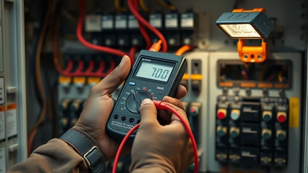
Check the upstream breaker or fuses first. Then confirm incoming line voltage is present and within the drive's rated range at L1/L2/L3, using your multimeter at the input terminals (with the drive still locked out per the previous section if you need to open the enclosure to reach them - verify with your meter, not by assumption). If incoming power is confirmed present and in range, move to the next check.
Control Power vs Main Power
A drive can have perfectly healthy main (motor) power and still show nothing on the display, because the keypad and control electronics run off a separate control power supply - not the same circuit that drives the motor.
Some PowerFlex models (many 525-series drives, for instance) derive control power internally from the main AC input, so if main power is present and the display is still dark, the internal control supply itself may be the problem. Other drives, particularly larger 750-series units, use a separate external 24VDC control power input that has to be verified independently - check your specific drive's power wiring diagram to know which applies. Test control voltage at its designated terminals with your multimeter; if it's absent or out of range, that's your lead, not the main power circuit.
When "No Display" Signals a Dead Drive
At some point, more checking stops being useful. If you've confirmed incoming line voltage is present and in range, confirmed control power is present and in range, and the display is still completely dark with no response to a power cycle, you're looking at a likely internal failure - a dead control board or a failed power supply - rather than a wiring problem you can fix in the field.
Other signals that point the same direction: a burnt smell, visible scorching on the control board through the vents, or a display that flickers and dies repeatedly on power-up. At that point, further troubleshooting mostly just burns time. We'll cover exactly how to weigh repair against replacement later in this guide - for now, just know that "confirmed power in, nothing out" is one of the clearest replace signals a technician can get.
If your drive does have a display and is showing an actual fault, the rest of this guide is built for you - starting with how to make sense of what you're looking at.
How PowerFlex Fault Reporting Works Across Series
Here's a question that trips up a lot of technicians: why does one drive show "Motor Overload" in plain English while another shows "F007" and nothing else? Both are correct - they're just different display conventions used across the PowerFlex family, and mixing up which convention applies to your drive is the fastest way to end up reading the wrong reference table.
Text-Based Names vs Numeric F-Codes
Every PowerFlex drive, regardless of series, assigns each fault an F-code number internally - that part is universal. What differs is what the keypad actually shows you. Drives with a simple integer LED-style display (the compact 4-Class and 40-Class units, and some legacy 700-series "Classic" drives) generally flash just the number, so unless you have that specific model's fault table on hand, F007 tells you nothing on its own. Drives with a fuller LCD or graphic HIM - including current 400/400P, 525, 753, and 755 units - display the plain-English fault name alongside the number, so you see "F007 - Motor Overload" directly on the screen.
The bigger trap is that the same F-code number does not always mean the same fault across series. F004 is Undervoltage on both the 400-series and the 525-series - that one lines up. But plenty of others don't: Analog Input Loss shows up as F029 on the 525-series, while a heatsink overtemperature fault is F008 on that same 525-series - not F029. On 750-series drives (700/750/753/755), several of these same fault concepts carry entirely different numbers again. If you search "PowerFlex F029" and pull up a table for the wrong series, you can walk away chasing the wrong problem.
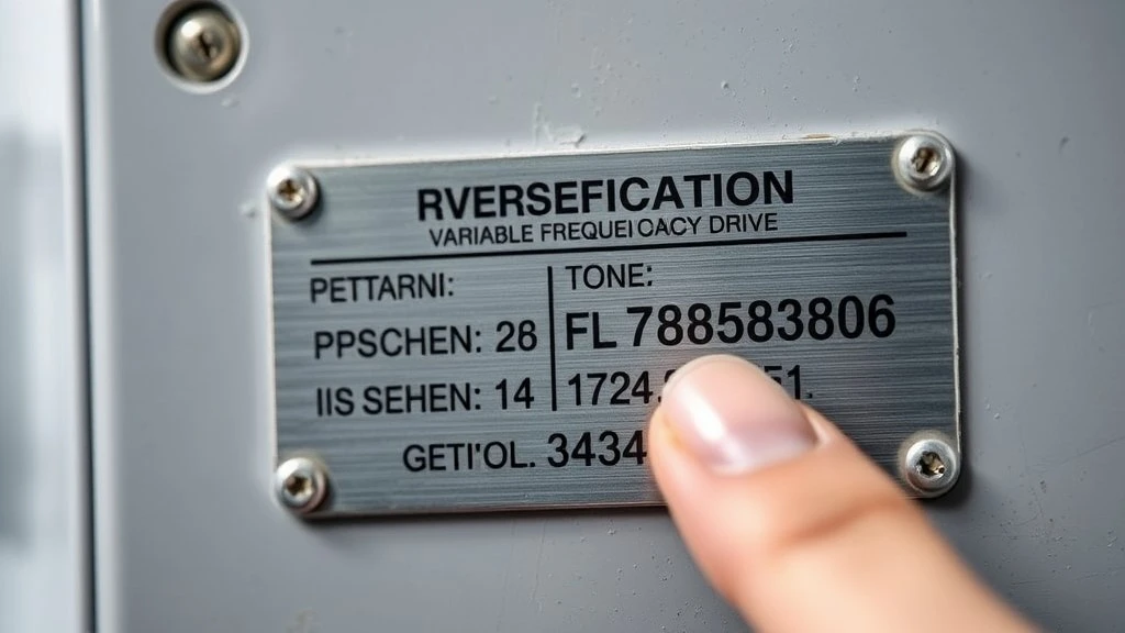
The fastest way to confirm which table applies to you: check the catalog number on your drive's nameplate. PowerFlex 525 catalog numbers start with 25B; 753 starts with 20F; 755 starts with 20G; 400/400P starts with 22C/22D. Match that prefix before you trust any fault code table - including the one in this guide.
|
Series |
Catalog prefix |
Display style |
|
PowerFlex 4/40 |
22A / 22B |
LED, number + abbreviated text |
|
PowerFlex 400 / 400P |
22C / 22D |
LED, number + abbreviated text |
|
PowerFlex 525 |
25B |
Full LCD/graphic HIM, number + full text |
|
PowerFlex 700 |
20B / 20F (Classic) |
Varies by HIM option installed |
|
PowerFlex 753 |
20F |
Full LCD/graphic HIM, number + full text |
|
PowerFlex 755 |
20G |
Full LCD/graphic HIM, number + full text |
Where to Find the Fault Queue by Series
Every PowerFlex drive keeps a short history of recent faults, which is worth checking even after you've cleared the active one - a fault that's shown up three times in the queue this week is a different problem than one that's shown up once. On 525-series drives, the fault queue is typically accessed through parameter A07 on the keypad, or through the fault history parameters if you're reviewing it in CCW. On 750-series drives, the fault queue lives in the diagnostic parameters accessible from the HIM's fault display menu or through Studio 5000 if the drive is networked.
If you're not sure which parameter number applies to your specific drive, CCW and Studio 5000 both give you a menu-driven path to the fault log without needing to memorize a parameter number - worth using if you're new to a particular series.
|
Series |
Where to check |
Software option |
|
PowerFlex 525 |
Parameter A07 (keypad) |
CCW |
|
PowerFlex 753 / 755 |
HIM diagnostics menu |
Studio 5000 / CCW |
|
PowerFlex 400 / 400P |
Fault history parameters |
- (standalone keypad access) |
Fault vs Alarm
Not every message on the display means the drive has stopped. A fault trips the drive - the motor stops, and you need to clear the fault before it will run again. An alarm is a warning condition that the drive flags but keeps running through, at least for a while.
The practical difference: an F-code means your line is already down. An alarm means you still have time to act before it becomes a fault. Treat alarms as an early-warning system, not background noise - a temperature or load alarm today is often the fault code you'll be dealing with next week if it's ignored.
Top PowerFlex Fault Codes - Causes and Fixes
These are the fault codes field technicians run into most often across the PowerFlex family. Each entry follows the same format - what it means, what causes it (most common first), how to fix it, and which series it applies to - so you can jump straight to the code on your display without reading the rest of the article.
F004 - Undervoltage
The drive's DC bus voltage dropped below its minimum operating threshold - on 480V input drives, that's typically somewhere around 380V DC. The most common cause is genuinely outside your control: a sag or brief interruption on the incoming line, often caused by another large load (a welder, a big motor starting) sharing the same feed. Loose or corroded input terminals and undersized supply feeders can produce the same symptom, and those you can fix.
Start by checking input terminal torque and condition, then monitor incoming line voltage with a meter - ideally over time, since a momentary sag won't show up in a single snapshot reading. If the supply itself is genuinely unstable, that's a power-quality issue upstream of the drive, and no amount of drive-side troubleshooting will make it go away - you may need to involve whoever manages the facility's power distribution. Applies across the 400, 525, and 750-series families, though the exact fault number and undervoltage threshold vary by series and input voltage rating - confirm against your drive's manual.
F005 - Overvoltage
Don't confuse this with F004 above - same underlying system (the DC bus), opposite direction. F005 trips when bus voltage climbs above its maximum threshold, commonly caused by the motor regenerating energy back into the drive during a fast deceleration, or by transient spikes on the incoming line.
If the cause is regeneration, your options split by cost: extending the deceleration time is a free parameter change and often solves it outright. If the application genuinely needs a fast stop, you'll need a dynamic braking resistor or chopper - that's a hardware addition, not a settings tweak, so it's worth confirming which situation you're in before you order parts. If the cause is line-side transients rather than regeneration, check for other equipment on the same feed causing the spikes. Applies across the same series as F004.
F007 - Motor Overload
This is one of the most commonly misdiagnosed faults on the list. The instinct is to suspect the motor itself, but in practice the single most common cause is a data entry problem: the motor nameplate parameters programmed into the drive (current, voltage, service factor) don't actually match the motor connected to it - often because the drive was swapped, reprogrammed, or commissioned with generic defaults instead of the real nameplate values.
Before you touch the mechanical side, pull up the motor overload current parameter and compare it against the actual motor nameplate. If they don't match, correct the parameter first - that alone resolves a large share of F007 trips. If the parameters check out, then look at the load itself: an actual excess load, a boost setting that's too aggressive for the application, or a partially seized mechanical component drawing extra current. Applies broadly across PowerFlex series, generally under the same or a very similar code number.
F012 - Hardware Overcurrent
The drive detected output current exceeding its instantaneous hardware limit - a harder, faster trip than the overload protection in F007 above. This is the fault most likely to point toward actual drive hardware damage rather than a field-fixable condition, so it's worth reading carefully.
Start with the field-fixable causes: a sudden mechanical load spike (a jam, a stuck conveyor), acceleration times set too aggressively for the load's inertia, or a boost parameter set too high. Check these first since they're free to rule out. But if you've confirmed the motor and mechanical load are healthy, the acceleration and boost settings are reasonable, and F012 keeps recurring anyway, that pattern points toward a degrading IGBT or gate driver inside the drive - a hardware failure, not a settings problem. That's a strong signal worth carrying into the repair-vs-replace decision covered later in this guide. Applies across 400/525/750-series drives, with number and exact threshold varying by series.
F013 - Ground Fault
The drive detected a current path to earth ground at one or more output terminals - current is leaking somewhere it shouldn't be, between the drive output and the motor. This is a safety-relevant fault; don't just reset it and walk away without checking the cause.
This is exactly where the megohmmeter from your tools list earns its keep. Disconnect the motor leads at the drive (with the drive locked out and discharged per the safety section above) and megger-test each motor phase to ground individually. A low insulation reading on any phase points to damaged motor winding insulation or damaged cable insulation - not a drive parameter issue. On long cable runs specifically, nuisance ground-fault-like trips can also stem from cable capacitance rather than a genuine insulation failure; if your megger readings come back clean but the fault persists on long runs, an output reactor is worth investigating. Applies across PowerFlex series, with the specific fault number varying - confirm against your drive's table.
F029 - Heatsink Overtemperature (number varies by series - see note below)
The drive's heatsink or power module has exceeded its rated operating temperature. This one connects directly back to the maintenance checklist later in this guide, because it's frequently a symptom of deferred cleaning rather than a sudden failure.

Start with the fan - confirm it's actually spinning and listen for bearing noise. Then check the heatsink fins for dust, oil mist, or debris buildup, which is extremely common on shop floors and quietly chokes airflow over months until the drive finally trips. Also confirm ambient temperature around the enclosure hasn't crept above the drive's rated range, especially in enclosures without adequate ventilation. If fans and airflow both check out and the fault still recurs, a failing temperature sensor is possible, though less common than a genuine airflow or cooling issue. Note: heatsink overtemperature is F008 on 525-series drives specifically - the F029 designation applies on other series. Always confirm the number against your drive's catalog prefix before troubleshooting.
F038 - Output Phase Loss (number varies by series - see note below)
The drive has detected a loss of one output phase to the motor - current isn't balanced across all three motor leads. This is a different failure mode than the input-side power issues covered earlier in the "No Display" section: this fault means the drive is running and outputting power, but something between the drive output and the motor windings has an open connection.
With the drive locked out, use your multimeter to check resistance across all three motor phases - they should read close to equal values. A phase reading dramatically different from (or open compared to) the other two points to a bad motor winding, a broken conductor, or a loose output terminal connection, rather than a drive problem. Applies across PowerFlex series; on 525-series drives this fault typically appears under a different number (F021), so check your series-specific table.
F040 - Analog Input Loss (number varies by series - see note below)
An analog input signal (commonly a 4-20mA or 0-10V speed reference) that the drive expects to see has dropped out or gone out of range. Don't confuse this with a parameter configuration error - this fault specifically means a signal that was present is now missing, not that a parameter value is wrong.
Check the physical wiring at the analog input terminals first - a loose screw terminal or a broken shield connection is the most common cause. If wiring checks out, confirm the sourcing device (PLC analog output card, transmitter, potentiometer) is actually generating the expected signal, and cross-check the analog input scaling parameters to make sure the drive is configured for the correct signal range (4-20mA vs 0-10V is a common mismatch). Applies across PowerFlex series; on 525-series drives this fault shows up under a different number (F029) - another reason to confirm your series before reading a code as gospel.
F100 - Parameter Default/Checksum
The drive's internal check of its stored parameter values didn't match what it expected - the parameter data has become corrupted. Unlike most of the faults above, this one points at internal memory hardware rather than field wiring or the motor.
The immediate fix is usually to reset the drive to factory defaults and reprogram it - which is exactly why backing up your parameter set (via CCW or Studio 5000) before you need it is worth doing on any drive that's been commissioned and tuned. If F100 clears after a reset and reprogram and stays cleared, you're likely fine. But if it comes back repeatedly without you having made any changes, that's a strong indicator of aging or failing non-volatile memory (NVRAM) hardware inside the drive - a condition that a parameter reset only masks temporarily, not a genuine fix. Recurring F100 is one of the more reliable "this drive needs replacing" signals covered in the decision framework below. Applies across PowerFlex series under this or a closely related fault number.
F064 - Safe-Off / STO Fault
This one connects directly back to the safety section at the top of this guide. A Safe Torque Off (STO) fault means the drive's safety circuit has removed the ability to generate motor torque - either because a genuine safety input was triggered (an E-stop, a guard door, a light curtain) or because the STO circuit itself isn't configured or wired the way the drive expects.
Start by ruling out the obvious: has a legitimate safety device actually been triggered? If so, that's the system working as designed, not a fault to troubleshoot around. If no safety device was triggered and the fault persists, check that STO inputs are wired and jumpered per your drive's safety documentation - some drives require a jumper across the STO terminals if the safety function isn't being used, and a missing or loose jumper alone can cause a persistent trip. Do not jumper or bypass the safety circuit as a troubleshooting shortcut if you're not certain what you're disabling - STO exists to prevent unexpected motion, and defeating it incorrectly can put someone in the path of a machine that starts unexpectedly. If you're not confident in the safety wiring, this is worth escalating rather than working through alone. The exact fault number varies meaningfully by series - F059 on many 525-series drives, and numbers in the F210 range on 750-series drives - so treat "F064" as a description of the fault type rather than a fixed number across all series.
Fault Code Quick Reference
|
Code |
Fault |
Most Likely Cause |
First Action |
|
F004 |
Undervoltage |
Line sag / loose input terminals |
Check terminals, monitor line voltage |
|
F005 |
Overvoltage |
Motor regeneration / line transients |
Extend decel time or add braking resistor |
|
F007 |
Motor Overload |
Wrong motor nameplate parameters |
Verify parameters match motor nameplate |
|
F012 |
Hardware Overcurrent |
Load spike / boost setting / IGBT wear |
Check load and settings; suspect hardware if recurring |
|
F013 |
Ground Fault |
Damaged motor/cable insulation |
Megger-test motor phases to ground |
|
F029* |
Heatsink Overtemp |
Dirty heatsink / failed fan |
Inspect fan and clean fins |
|
F038* |
Output Phase Loss |
Broken motor lead/winding |
Check phase-to-phase resistance |
|
F040* |
Analog Input Loss |
Loose signal wiring |
Check terminal and signal source |
|
F100 |
Parameter Checksum |
Corrupted parameter memory |
Reset to defaults, reprogram, restore from backup |
|
F064* |
Safe-Off / STO |
Safety input triggered / miswired |
Confirm safety device state, check jumpers |
*Number varies by series - confirm against your drive's catalog prefix before troubleshooting.
Fault codes tell you the symptom. They don't always tell you why the same fault keeps coming back - that's a different kind of question, and it's the one the next section answers.
Physical Root Causes Behind Recurring Faults
If you've cleared the same fault two or three times this month, the fault code itself has already told you what's happening. What it hasn't told you is why. These are the physical conditions behind the fault codes above that keep bringing technicians back to the same drive.
Bound or Excess Mechanical Load
A mechanical problem doesn't always show up as a mechanical fault - it often shows up as an electrical one. A binding bearing, a jammed conveyor, a seized coupling, or a failing fan all force the motor to draw more current than it should, and that current draw is exactly what triggers F007 or F012. If either of those codes keeps recurring and the electrical side checks out clean, the load itself is worth a physical inspection before you spend more time on drive parameters.
One specific trap worth knowing: autotuning a drive with the motor still coupled to its load can produce inaccurate tuning results, which then shows up later as nuisance overload or overcurrent trips that look electrical but actually trace back to that mistuning. If a drive has a history of unexplained F007/F012 trips, it's worth checking whether the autotune was performed with the load disconnected as intended.
Cable Wear and Connection Issues
Beyond the motor and load, the cable run and its terminations degrade over time - vibration loosens terminals, and repeated flexing or heat cycling wears insulation. That degradation shows up as intermittent faults that are maddening to chase because they don't happen every time.
Check the physical connection points, including the DPI communication ports if your drive uses them for peripheral connections - each port on a 525 or 750-series drive typically has a defined function, so confirming a device is seated in the correct port is worth ruling out before assuming a bad cable. Note that this is specifically about the physical cable and connector layer; if the symptom is a networked communication dropout rather than a loose terminal, that's more likely the F043-type communication fault covered in the fault code section above - rule out the physical layer first, then move to network diagnostics if the problem persists.
Corrosion and Moisture Damage
Humidity and airborne chemicals do slow, cumulative damage to circuit boards and connections - this is a different failure mode than the temperature issue covered next, so it's worth treating separately even though both are "environmental."
Moisture and chemical exposure typically shows up as corrosion on terminals and board contacts, which increases resistance at connection points and can eventually contribute to overvoltage or overtemperature-type trips as components degrade. Enclosures in wash-down areas, near chemical processes, or in humid, poorly ventilated spaces are the highest-risk locations. Dehumidification, adequate enclosure sealing (matching the IP/NEMA rating to the environment), and keeping enclosure doors closed when not actively being worked on all reduce this risk over time - how often to actually inspect for it is covered in the maintenance checklist below.
Ventilation and Ambient Temperature
This is the temperature half of the environmental picture, and it connects directly back to the F029/F008-type heatsink overtemperature fault covered earlier - this section is really that fault's root-cause detail, not a separate topic.
Give the drive the clearance called out in its installation manual - crowding a drive against other equipment or enclosure walls restricts the airflow it's designed around. Keep ambient temperature within the drive's rated range; most PowerFlex drives are rated for a maximum ambient somewhere in the 40-50°C range depending on model and derating requirements, but confirm the specific number for your unit rather than assuming. If a drive is installed in a tight, poorly ventilated cabinet, supplemental cabinet cooling is often cheaper than the repeated heatsink faults (and eventual hardware wear) that come from running consistently hot.
Understanding why a fault keeps happening is half the job. Actually clearing it - safely, and in the right way for how your system is set up - is the other half.
How to Clear a Fault
Once you've identified and corrected the cause, the drive still needs to be told the fault is resolved before it will run again. There are three ways to do that, and which one fits depends on how the drive is set up.
From the Keypad/HIM
The simplest and most universal method: press Stop/Reset directly on the drive's keypad or HIM. This works on every PowerFlex series and doesn't require any software or network connection.

One important thing to understand: if you press reset and the fault immediately reappears, that means the underlying condition is still present - you haven't actually fixed the cause yet, you've just acknowledged the symptom. Don't keep pressing reset hoping it eventually sticks; go back and re-verify the root cause instead.
From Software (CCW / Studio 5000)
If the drive is networked, you can clear faults remotely without walking to the panel. In Connected Components Workbench, this is typically a right-click "Clear Faults" action from the drive's diagnostic view. In Studio 5000, clearing a fault is done by writing to the drive's Logic Command register through the controller tags.
If you're not familiar with either piece of software, the keypad method above works exactly the same and doesn't require learning a new tool under time pressure - save the software route for drives you're already comfortable navigating remotely.
Via Digital Input (PLC-Controlled)
For systems where a PLC manages drive operation as part of a larger automated sequence, a digital input can be configured to trigger a fault reset automatically, without a person pressing anything. This is common in applications where the drive is one component in a fully automated line and manual intervention for every fault isn't practical.
This approach isn't appropriate for every application - configured incorrectly, it means the drive can restart without a person confirming it's actually safe to do so. That risk is exactly what the next section is about.
Manual Reset vs Auto-Restart - Which Should You Use?
This is a judgment call, not a technical preference - and it's one place we'll give you a direct answer rather than a "depends on your situation." Any application where an unexpected restart could put a person at risk should use manual reset, full stop. Auto-restart is a productivity feature, not a default setting, and it should only be enabled where an unattended restart is genuinely safe.
Picture a conveyor that auto-restarts after a fault clears, with a technician's hand still near the belt investigating what tripped it in the first place. That scenario is exactly why this decision needs to be made deliberately, application by application, rather than left on whatever the drive shipped with.
|
Scenario |
Recommended |
Why |
|
Personnel work near the machine during operation |
Manual reset |
Unexpected restart is a safety hazard |
|
Unattended process equipment, no personnel access during run |
Auto-restart (with limited retry count) |
Minimizes downtime with no safety exposure |
|
Safety-rated stop (STO, E-stop related faults) |
Manual reset - always |
Safety functions should never auto-clear |
|
Nuisance trips on non-hazardous equipment (e.g., minor undervoltage blips) |
Auto-restart may be appropriate |
Reduces unnecessary intervention for low-risk faults |
If you do use auto-restart, limit the number of retry attempts and set a reasonable delay between them - a drive that auto-restarts endlessly against a fault that isn't clearing just repeats the failure mode instead of catching it.
Clearing a fault gets the line moving again today. Whether it stays running next month is mostly a maintenance question.
Preventive Maintenance Checklist
Most of the faults covered in this guide are preventable with a maintenance routine that costs a few minutes a week. These checks are organized by how often they're worth doing - start simple and visual, build up to instrumented testing.
Weekly Checks
- Listen for unusual fan or bearing noise
- Confirm cooling fan is actually spinning
- Visually check for dust or debris buildup on heatsink fins/vents
- Confirm HIM display and status LEDs are functioning normally
- Check for any active alarms in the queue, even if the drive is currently running fine
Quarterly Checks
- Clean heatsink fins and enclosure vents thoroughly
- Check and re-torque power terminal connections
- Back up drive parameters (via CCW or Studio 5000)
- Inspect enclosure door seals and gaskets for wear
- Verify ambient enclosure temperature is within rated range
- Review the fault queue history for any recurring codes
Annual Checks
- Megohmmeter insulation resistance test on motor leads
- DC bus capacitor health evaluation
- Full torque check on all power and control connections
- Verify safety circuit (STO) function if equipped
- Confirm control power backup/battery status if applicable
Some annual checks - particularly capacitor health evaluation and safety circuit verification - are worth having performed by a qualified service technician if you don't have the specialized test equipment or training in-house, rather than skipping them.
Good maintenance catches most problems before they become fault codes. But eventually, on any drive, you'll hit a fault that maintenance can't prevent - and at that point, the question changes from "how do I fix this" to "is fixing this even the right call."
Repair or Replace? A Decision Framework
Every fault code and root cause covered so far has been building toward this question, because at some point the honest answer to "how do I fix this" is "you probably shouldn't." Here's how to make that call without guessing.
Signs You Need a Replacement Drive
A few patterns from earlier in this guide are worth pulling together here, because individually they're troubleshooting steps and collectively they're a replacement decision:
- F012 (Hardware Overcurrent) recurring with confirmed-good motor, load, and wiring - points to IGBT or gate driver degradation inside the drive itself
- F100 (Parameter Checksum) recurring after a reset and reprogram, with no configuration changes made - points to failing internal memory hardware
- No display, with confirmed-good incoming power and control power - points to a dead control board or internal power supply
- Visible physical damage - scorching, burnt smell, or component discoloration visible through the enclosure vents
- Repeated resets required for the same fault within a short window, even after root-cause troubleshooting has come up clean
If you're seeing one or more of these, further field troubleshooting is more likely to burn time than solve the problem. That's the point to start pricing a replacement rather than continuing to chase it.
How to Verify You're Buying a Genuine PowerFlex Replacement
The used and refurbished VFD market has real value, but it also has a real counterfeit and mislabeled-parts problem - and putting a fake or mismatched drive into a critical process is a worse outcome than the original fault. A few checks before you buy protect you either way:
- Cross-check the full catalog number, series, and rating on the nameplate against the listing - not just the model family, but the complete part number
- Verify serial number authenticity where the supplier offers it - legitimate sellers of genuine Allen-Bradley/Rockwell parts are generally able to confirm this
- Ask about the supplier's return and warranty terms - a supplier confident in what they're selling will stand behind it in writing
- Be cautious of prices dramatically below market - a price that looks too good relative to comparable listings is a real signal, not just a good deal
- Confirm firmware/hardware revision compatibility with your existing configuration, especially if you're replacing one unit in a networked system where parameter files need to carry over
If you're sourcing a replacement, browsing our current Allen-Bradley PowerFlex inventory is a reasonable next step once you've confirmed the exact catalog number you need.
Why Sourcing Speed Matters When Production Is Down
Once you've decided to replace rather than repair, how fast you can get the part matters as much as getting the right part. A line-down hour has a real cost - lost output, idle labor, and often contractual penalties on top of the direct loss - and that cost accumulates for every hour spent waiting on a slow order, regardless of how good the eventual part turns out to be.
The practical trade-off is standard lead time through a typical order channel versus a supplier that holds the specific catalog number in stock and can ship same-day. For a spare that's likely to fail eventually anyway, having it identified and sourced before it's an emergency is the version of this that actually saves money - the alternative is making a sourcing decision under the worst possible time pressure.
FAQ

What is the most common PowerFlex fault code?
How do I find the fault history on a PowerFlex drive?
Why does my PowerFlex drive keep tripping on overvoltage/undervoltage?
Can I reset a PowerFlex fault remotely via PLC?
What's the difference between a PowerFlex fault and an alarm?
How long should I wait before touching a PowerFlex drive after power-off?


