


Connecting an Omron HMI (Human - Machine Interface) to an Omron PLC (Programmable Logic Controller) is a fundamental process in industrial automation systems. As an established Omron PLC supplier, I will walk you through the step - by - step process of achieving this connection and provide some important considerations along the way.
Understanding the Basics
Before embarking on the connection process, it's essential to understand the roles of the HMI and the PLC. The Omron PLC serves as the brain of the automation system. It controls the operation of various industrial equipment by executing pre - programmed logic. For example, an Omron CJ1M - CPU21 PLC can manage complex manufacturing processes such as assembly lines.
On the other hand, the Omron HMI is the interface through which operators interact with the PLC. It allows users to monitor the system status, input commands, and adjust parameters. By connecting the two, operators can effectively control and monitor the automation system.
Selecting the Right Communication Method
Omron offers multiple communication methods for connecting HMIs to PLCs, and the choice depends on several factors, including the distance between the devices, the data transfer rate requirements, and the overall system complexity.
Ethernet Communication
Ethernet is a popular choice for its high - speed data transfer capabilities and long - distance communication. Many modern Omron HMIs and PLCs support Ethernet communication protocols such as EtherNet/IP. For example, if you have an Omron HMI and a PLC with Ethernet ports, you can connect them using an Ethernet cable. First, you need to ensure that both devices are configured with valid IP addresses within the same subnet. Then, configure the communication settings on the HMI and the PLC to use the appropriate Ethernet protocol.
Serial Communication
Serial communication is another option, especially for older Omron models or in situations where a simple and cost - effective connection is required. RS - 232 and RS - 485 are common serial communication standards. When using serial communication, you need to pay attention to parameters such as baud rate, data bits, stop bits, and parity. Make sure that these settings are consistent on both the HMI and the PLC.
Hardware Connection
Once you've selected the communication method, it's time to make the hardware connection.
For Ethernet Connection
- Obtain an appropriate Ethernet cable. Ensure that the cable is in good condition and has the correct pin - out for Ethernet communication.
- Connect one end of the Ethernet cable to the Ethernet port of the Omron HMI and the other end to the Ethernet port of the Omron PLC.
- If there are multiple devices on the network, you may need to use a network switch to connect them. Connect the HMI and the PLC to the switch using Ethernet cables.
For Serial Connection
- Select a suitable serial cable. For RS - 232 communication, use a DB9 cable. For RS - 485 communication, use a shielded twisted - pair cable.
- Connect the serial cable to the appropriate serial ports on the HMI and the PLC. Make sure to match the correct pins according to the communication standard.
Software Configuration
After the hardware connection is complete, you need to configure the software settings for both the HMI and the PLC.

PLC Configuration
- Open the Omron PLC programming software, such as CX - Programmer.
- Establish a connection to the PLC. You may need to specify the communication method (Ethernet or serial) and enter the relevant communication parameters.
- Configure the communication settings specific to the connection with the HMI. For example, if using Ethernet, set up the IP address, subnet mask, and gateway. If using serial, set the baud rate, data bits, stop bits, and parity.
- Define the data areas that will be exchanged between the PLC and the HMI. This may include input/output addresses, memory words, or other data registers.
HMI Configuration
- Launch the Omron HMI programming software, such as NS Designer.
- Create a new project and select the appropriate HMI model.
- Set up the communication settings to match those of the PLC. This includes specifying the communication method, IP address (for Ethernet), or serial parameters.
- Design the screens of the HMI, including buttons, indicators, and data displays. Link these objects to the corresponding data areas in the PLC. For example, you can create a button on the HMI that sends a command to the PLC to start a motor by writing a specific value to a designated memory address in the PLC.
Testing the Connection
After completing the hardware and software configurations, it's crucial to test the connection between the Omron HMI and the Omron PLC.
- Power on both the HMI and the PLC.
- Check the communication status indicators on both devices. If the communication is successful, the indicators should show a normal status.
- On the HMI, try to change some input values or send commands to the PLC. Then, check in the PLC programming software if the data is being received correctly.
- Monitor the output values on the HMI that are linked to the PLC data. Ensure that the values are updated in real - time as the PLC processes the data.
Considerations for Different Omron Models
Different Omron PLC models may have specific requirements or limitations when connecting to an HMI.
For instance, the Omron R88D - 1SN01H - ECT is a servo drive. When integrating it with a PLC and an HMI, you need to ensure that the communication protocol and data exchange mechanism are compatible. The PLC should be able to send appropriate control signals to the servo drive, and the HMI should be able to display the relevant status information.
The Omron C200HW - NC413 is a motion control unit. Connecting it to an HMI and a PLC requires careful configuration of the motion control parameters and the communication between the three devices.
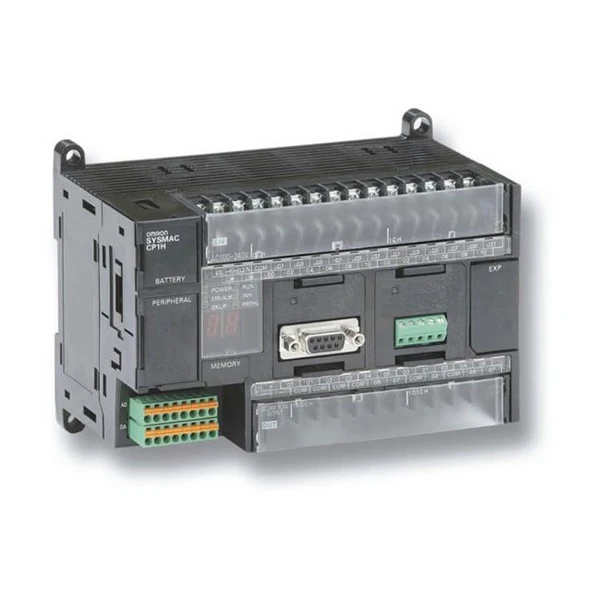
The CP1H - X40DR - A Omron is a compact PLC. It has limited communication ports and resources, so you need to optimize the communication settings to ensure efficient data transfer between the HMI and the PLC.
The OMRON CJ1W - II101 Interface Module can be used to expand the input/output capabilities of the PLC. When using this module, make sure that the HMI is configured to access the data from the expanded I/O points.
Troubleshooting
If you encounter problems during the connection process, here are some common issues and solutions:
Communication Failure
- Check the hardware connections. Make sure that the cables are properly plugged in and there are no loose connections.
- Verify the communication settings on both the HMI and the PLC. Ensure that the IP addresses, serial parameters, and communication protocols are consistent.
- Check if there are any network or serial port conflicts. For example, another device on the network may be using the same IP address.
Data Transfer Issues
- Check the data mapping between the HMI and the PLC. Make sure that the data areas are correctly defined and linked.
- If the data transfer rate is too low, consider changing the communication method or adjusting the communication parameters to increase the speed.
Conclusion and Call to Action
Connecting an Omron HMI to an Omron PLC is a multi - step process that requires a good understanding of both hardware and software configurations. By following the steps outlined in this blog, you can successfully establish a connection and create an efficient industrial automation system.
As an Omron PLC supplier, I have in - depth knowledge and experience in Omron products. Whether you need assistance with product selection, system configuration, or troubleshooting, I'm here to help. If you are interested in purchasing Omron PLCs, HMIs, or other related products, or if you have any questions about the connection process, feel free to reach out for a detailed consultation and procurement negotiation.
References
- Omron CX - Programmer User Manual
- Omron NS Designer User Manual
- Omron Device Communication Guides (Ethernet, Serial)


