


As a supplier of ABB PLC modules, I'm often asked about how to use the PID control function in these modules. PID, which stands for Proportional - Integral - Derivative, is a widely used control algorithm in industrial automation. It helps in maintaining a process variable at a desired setpoint by adjusting the control output. In this blog, I'll guide you through the steps of using the PID control function in ABB PLC modules.
Understanding the Basics of PID Control
Before diving into the implementation, it's essential to understand the three components of the PID controller:
- Proportional (P): This component provides an output that is proportional to the error between the setpoint and the process variable. A larger error will result in a larger control output. However, using only the proportional term can lead to a steady - state error, where the process variable never reaches the setpoint exactly.
- Integral (I): The integral term accumulates the error over time. It helps to eliminate the steady - state error by continuously adjusting the control output until the error is zero. But too much integral action can cause the system to overshoot and become unstable.
- Derivative (D): The derivative term calculates the rate of change of the error. It anticipates future changes in the error and helps to dampen oscillations. It is particularly useful in systems with rapid changes.
Selecting the Right ABB PLC Module
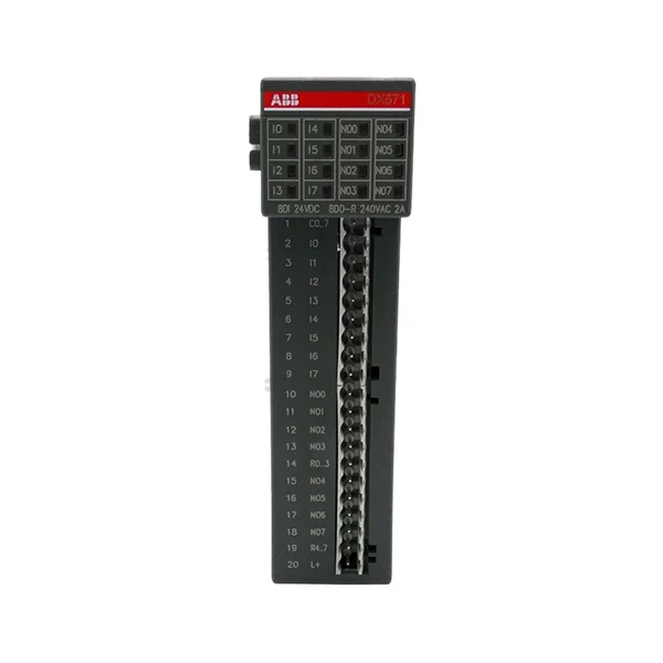
ABB offers a wide range of PLC modules that support PID control. For example, the ABB DX571 1TNE968902R2302 is a high - performance module suitable for various industrial applications. The ABB PM665 Processor Module also provides powerful processing capabilities for complex control tasks, including PID control. And the AI845 ABB Analog Input Module can be used to measure the process variable accurately.
Configuring the PID Controller in ABB PLC
The following steps outline the general process of configuring a PID controller in an ABB PLC module:
Step 1: Define the Process Variable and Setpoint
The first step is to identify the process variable that you want to control. This could be temperature, pressure, flow rate, etc. You also need to define the setpoint, which is the desired value of the process variable. In the ABB PLC programming environment, you'll need to allocate memory locations for the process variable input and the setpoint.
Step 2: Select the PID Function Block
ABB PLC programming software provides pre - defined PID function blocks. You need to select the appropriate function block based on your application requirements. These function blocks typically have input parameters for the process variable, setpoint, and the PID gains (proportional, integral, and derivative).
Step 3: Set the PID Gains
Tuning the PID gains is a critical step. There are several methods for tuning, such as the Ziegler - Nichols method. The Ziegler - Nichols method involves finding the ultimate gain and the ultimate period of the system and then calculating the PID gains based on these values. In the ABB PLC, you can adjust the PID gains within the function block parameters.
Step 4: Configure the Output
The output of the PID controller is used to adjust the control element, such as a valve or a motor. You need to configure the output range and the type of output (analog or digital). In the ABB PLC, you'll map the output of the PID function block to the appropriate output module.
Step 5: Implement Error Handling
It's important to implement error handling in your PID control program. For example, if the process variable goes out of a safe range, the system should take appropriate action, such as shutting down the control element or generating an alarm.
Testing and Tuning the PID Controller
Once you've configured the PID controller, you need to test it in a real - world environment. Start by running the system with conservative PID gains and gradually adjust them based on the system's response. Observe the following aspects during testing:
- Response Time: The time it takes for the process variable to reach the setpoint. A shorter response time is generally better, but it should not cause excessive overshoot.
- Overshoot: The amount by which the process variable exceeds the setpoint. Minimizing overshoot is crucial for system stability.
- Steady - State Error: The difference between the setpoint and the process variable after the system has reached a steady state. The integral term of the PID controller should help to reduce this error to zero.
Monitoring and Maintenance
After the PID controller is up and running, continuous monitoring is essential. You can use the ABB PLC's diagnostic features to monitor the performance of the PID controller. Look for any signs of instability, such as oscillations or large steady - state errors. Regular maintenance includes checking the input and output modules for proper operation and updating the PID gains if the system characteristics change over time.
Conclusion
Using the PID control function in ABB PLC modules can significantly improve the efficiency and stability of industrial processes. By following the steps outlined in this blog, you can successfully configure, test, and maintain a PID controller in your ABB PLC system. If you're interested in purchasing ABB PLC modules for your PID control applications or have any technical questions, feel free to reach out for a detailed discussion. We're here to provide you with the best solutions and support for your industrial automation needs.
References
- ABB PLC Programming Manuals
- Industrial Automation Handbook on PID Control
- Ziegler, J. G., & Nichols, N. B. (1942). Optimum settings for automatic controllers. Transactions of the ASME, 64(8), 759 - 768.


