


Hey there! As a supplier of Mitsubishi VFDs, I've had my fair share of experiences with these amazing devices. One of the most useful features in many Mitsubishi VFDs is the built - in PID controller. In this blog, I'm gonna walk you through how to use it effectively.
First off, let's quickly understand what a PID controller is. PID stands for Proportional, Integral, and Derivative. It's a control algorithm that helps in maintaining a process variable at a setpoint. In the context of a VFD, it can be used to control things like speed, pressure, or temperature.
Step 1: Understanding Your VFD Model
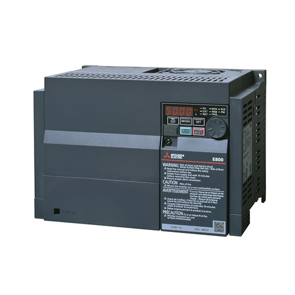
Mitsubishi offers a wide range of VFDs, each with its own set of features and functions. For example, the Mitsubishi Electric FR - E840 - 0120 - 4 - 60 is a high - performance drive suitable for various industrial applications. Another popular model is the Mitsubishi FR - E740 - 0.4K - CHT, which is more compact and cost - effective. And the FR - A840 - 00170 - 2 - 60 Mitsubishi is known for its advanced control capabilities.
Before you start using the PID controller, you need to know the specific settings and parameters for your VFD model. Check the user manual that comes with your drive. It'll have all the details about how to access and configure the PID controller.
Step 2: Setting Up the PID Controller
Once you've familiarized yourself with your VFD model, it's time to set up the PID controller. Here are the general steps:
Set the Setpoint
The setpoint is the value you want the process variable to reach. For example, if you're using the VFD to control the speed of a motor, the setpoint could be a specific RPM. You can usually set the setpoint through the VFD's keypad or a programming tool.
Configure the Input Signal
The PID controller needs an input signal that represents the current value of the process variable. This could be a voltage or current signal from a sensor. You'll need to select the appropriate input source in the VFD settings. Make sure the signal range of the sensor matches the input range of the VFD.
Adjust the PID Gains
The three main gains in a PID controller are the proportional gain (P), integral gain (I), and derivative gain (D).
- Proportional Gain (P): This gain determines how much the controller output changes in proportion to the error between the setpoint and the process variable. A higher P gain will make the controller respond more quickly to errors, but it can also cause overshoot.
- Integral Gain (I): The integral gain is used to eliminate the steady - state error. It accumulates the error over time and adjusts the controller output accordingly. However, a too - high I gain can lead to instability.
- Derivative Gain (D): The derivative gain helps in predicting the future behavior of the process variable. It reduces overshoot by damping the system response.
Finding the right values for these gains can be a bit tricky. You may need to do some trial and error, starting with conservative values and gradually adjusting them based on the system's response.

Step 3: Testing and Tuning
After setting up the PID controller, it's time to test it. Start the VFD and observe how the process variable responds to the setpoint. Here are some things to look out for:
Overshoot
Overshoot occurs when the process variable exceeds the setpoint. If you notice significant overshoot, you may need to reduce the P gain.
Steady - State Error
A steady - state error is the difference between the setpoint and the process variable after the system has settled. If there's a steady - state error, you can increase the I gain to eliminate it.
Response Time
The response time is how quickly the process variable reaches the setpoint. If the response is too slow, you can increase the P gain or adjust the D gain.
Keep making small adjustments to the PID gains and testing the system until you get the desired performance.
Step 4: Monitoring and Maintenance
Once the PID controller is up and running, it's important to monitor its performance regularly. Check the process variable values and make sure they're within the acceptable range. Also, keep an eye on the VFD's operating parameters, such as temperature and current.
If you notice any issues, like abnormal fluctuations in the process variable or overheating of the VFD, take appropriate action. It could be a sign of a faulty sensor, incorrect PID settings, or a problem with the VFD itself.
Tips and Tricks
- Use Auto - Tuning: Some Mitsubishi VFDs have an auto - tuning function for the PID controller. This can save you a lot of time and effort in finding the right PID gains. Just follow the instructions in the user manual to use this feature.
- Document Your Settings: Keep a record of all the PID settings and parameters you've configured. This'll be helpful if you need to troubleshoot or make changes in the future.
- Get Training: If you're new to using PID controllers, consider getting some training. Mitsubishi offers training courses and resources that can help you become more proficient in using their VFDs.
Conclusion
Using the built - in PID controller of a Mitsubishi VFD can greatly enhance the performance and efficiency of your industrial processes. By following the steps outlined in this blog, you can set up and tune the PID controller effectively.
If you're interested in purchasing a Mitsubishi VFD or need more information about using the PID controller, feel free to reach out. We're here to help you with all your VFD needs. Whether you're a small business or a large industrial operation, we can provide the right solutions for you.
References
- Mitsubishi Electric VFD User Manuals
- Industrial Control System Literature on PID Controllers


